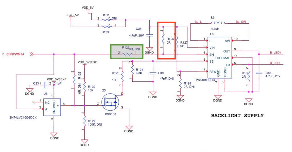
To enable backlight dimming using the CircuitCo LCD3 cape, you need to connect the backlight boost circuit EN line to EHRPWM1A, by removing R126 and adding a 0R resistor (or blob of solder) to the pads for R123.
The Beaglebone Black is a palm-sized computer for electronics hobbyists, designed by Gerald Coley, charter member of Beagleboard.org. Development is supported by an open source community, with the help of Texas Instruments (which manufactures the BBB’s embedded MPU, the AM3358).
If you’ve been struggling to get the Beaglebone LCD3 cape working with the mainstream Linux kernel releases from kernel.org, the first thing you need to know is that it can be done. The key to making this work is to understand that dynamic cape loading isn’t yet supported in the mainline tree (but see Robert C. Nelson’s guide at elinux.org for a guide to building a special branch that does support dynamic cape load and unload. Kernel 3.8+ works with the LCD3 cape). There are a lot of people still working on cleaning up the code to meet kernel maintainers’ criteria for acceptance. Until that happens, we’ll have to make do by cobbling together a custom devicetree source file to support devices which don’t yet run out of the box, using the mainline kernel source.
What works
Resistive touch screen using the AM3358 A/D converters
All five GPIO user buttons
GPIO-driven user LED
Backlight
And, of course, the TFT LCD itself
I’ll assume that you’re able to compile a Linux kernel, and have got around to doing so a few times for your BBB. These instructions apply to the stable Linux kernel 3.16.1, but should be straightforward to apply to other (recent) releases which support the Direct Rendering Manager interfaces and ARM device trees.
I’d recommend that you install this newly compiled kernel onto an SD card filesystem, rather than use the BBB’s onboard eMMC storage. Be warned that the kernel configuration file I’ve provided with this guide is taken from my own working system, which I use as a router – there’s a lot of firewall, bridging, etc., other networking-related modules built (and built-in) which may not be suitable for general use.
Steps
Power down and detach the LCD3 cape from your BBB.
Run make ARCH=arm CROSS_COMPILE=arm-angstrom-linux-gnueabi- LOADADDR=0x80008000 uImage dtbs, etc. to build the kernel. Alternately, if you’ve set up an in situ build environment on your BBB, you can copy this build script into the kernel directory tree root and run ./build.sh. The script starts a complete build process starting with make menuconfig, to create a uImage-structured kernel and associated kernel modules.
Copy arch/arm/boot/dts/am335x-boneblack.dtb into the correct location for your BBB.
Restart your BBB to confirm that the kernel works for you. You’ll want to take a look at the output of dmesg to check which devices were initialized.
Power off, and mount the LCD3 cape.
Power up.
Under the hood
The provided patch simply enables a number of device tree nodes, representing devices on the ARM system-on-a-chip (SOC). The nodes that need to be exposed to the kernel to use the LCD3 cape are 1) the onboard A/D converter, 2) the enhanced high-resolution pulse width modulation subsystem (ehrpwmss), used for controlling the panel backlight, 3) general-purpose I/Os used to drive the user LED and provide interrupt-driven key events.
Note that the provided kernel configuration script enables a number of kernel features, the most important of which are
Support for touch panels using the AM3358 onboard A/D,
User input drivers for GPIO keys, and for building the evbug module (to aid debugging key press events), and
OMAP DSS DRM support.
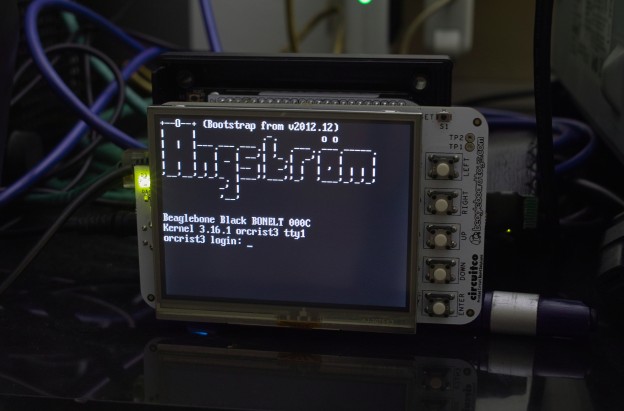
After rebooting your BBB with this new kernel, the LCD3 cape should become available as a framebuffer device /dev/fb0.
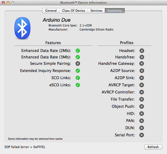
Update: RFCOMM negotiation works now – connecting to the serial TTY device enables use of one of the Arduino Due UARTs. You can send short strings across the Bluetooth SPP link. The hexadecimal dump below was apparently a Bluetooth dongle hardware error code, one byte “0x37” (0x10 0x01 0x37). Documentation from CSR (look for the document CS-227432-SP-3-BCCMD-HQ, by searching for “HQ Commands”) told me this was a hardware fault code with a funny name:
FAULT_ALREADY_BAGSIED: Two subsystems are attempting to use the same .
The same what? The PDF contains exactly that text, “… the same .” Nuts. The documentation was leading me nowhere, but clearly the dongle was receiving command data I was sending to it, and going into fault condition as a result.
It turned out that I was sending an incomplete RFCOMM packet – I forgot to include the HCI handle for the existing ACL connection in the command I was sending. Aargh…!
So, it works now, after a fashion. I’m able to connect to the UART to send very short strings. Trying to send anything longer in either direction will crash the dongle HCI stack, which says there’s still something wrong with the code. Get the updated code here, as well as the driver sketch here.
Some good news: The Atmel Software Framework 3.12 allows interrupt-driven reads and writes from any of the Bluetooth dongle pipes – control, event, and bulk I/O. This is good. Continue reading “Arduino Bluetooth Blues”
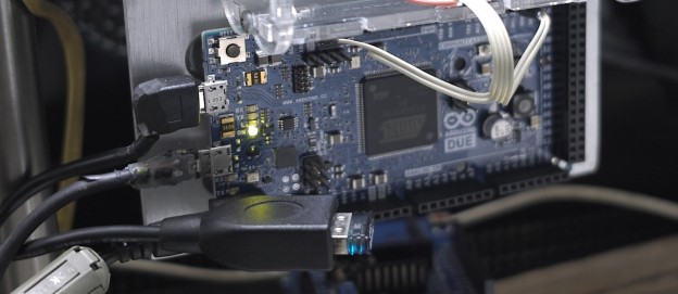
The Arduino Due uses an Atmel SAM3X8E microcontroller, and is capable of functioning as a USB host. Well, sort of: The USB Host library supplied with the Arduino IDE is apparently still a work in progress, so that it isn’t possible to attach a Bluetooth dongle and make it function as a BT serial adapter.
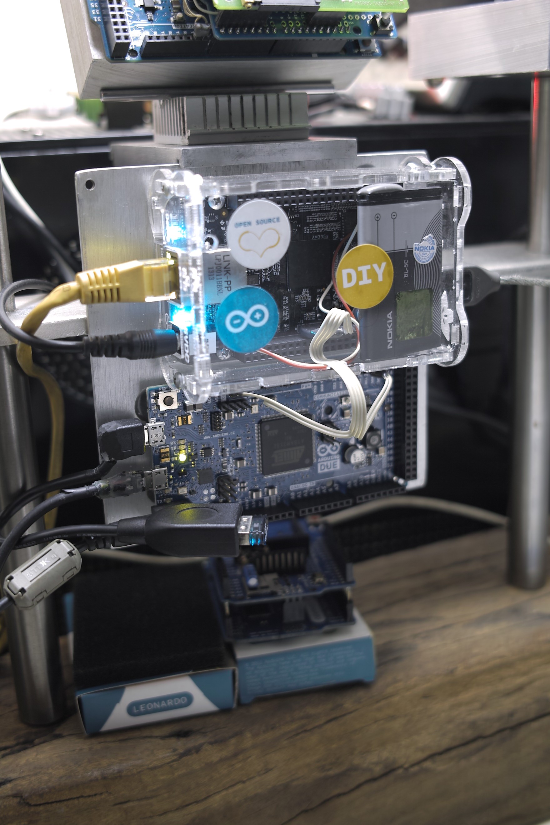
A Beaglebone and an Arduino epoxied to an aluminum plate.
My goal was to be able to use the Due as a wireless serial port, for a Beaglebone that I wanted to use for a CNC controller project. It took three days of poring through the source code in /Applications/Arduino.app, the SAM3X8E technical reference manual, the USB 2.0 specification, and the Bluetooth 4.0 Core Specification to learn several things:
The Arduino USBHost library is definitely work in progress – the USB Host Shield 2.0 library created by Kristian Lauszus of TKJ Electronics was written to work with another family of microcontrollers used in Arduinos (the Atmega AVRs). It doesn’t yet enable full use of the Arduino Due’s ‘native’ USB On-The-Go interface as a host interface;
There is enough Atmel-supplied support library code, bundled with the Arduino IDE, to extend Lauszus’ SPP (serial port profile) and BTD (Bluetooth Device) classes, if you were willing to hack at the code;
The USB Host Shield library Arduino code, when compiled for the Arduino Due, only speaks to endpoint zero, the USB control endpoint. Trying to read from the ill-named Interrupt endpoint (it’s actually polled) results in a timeout because initialization calls to set up data structures for endpoint zero were not applied to other endpoints on the Bluetooth device.
So what I ended up doing was extracting just three classes from Lauszus’ code – the SPP, BTD, and USBHost classes – and thrashing at the sample code to eventually yield this:
The Bluetooth dongle is attached to an Arduino Due using a USB OTG Host Cable, which in turn is powered by an external 12V power supply.
The code here (USBHost-Due-BT.tar.bz2, .tar.bz2) replaces the USB Host library. You can use a sketch similar to the one below to experiment with the library code (you’ll modify the .cpp and .h files containing classes SPP, BTD, and USBHost to hack the code into shape).
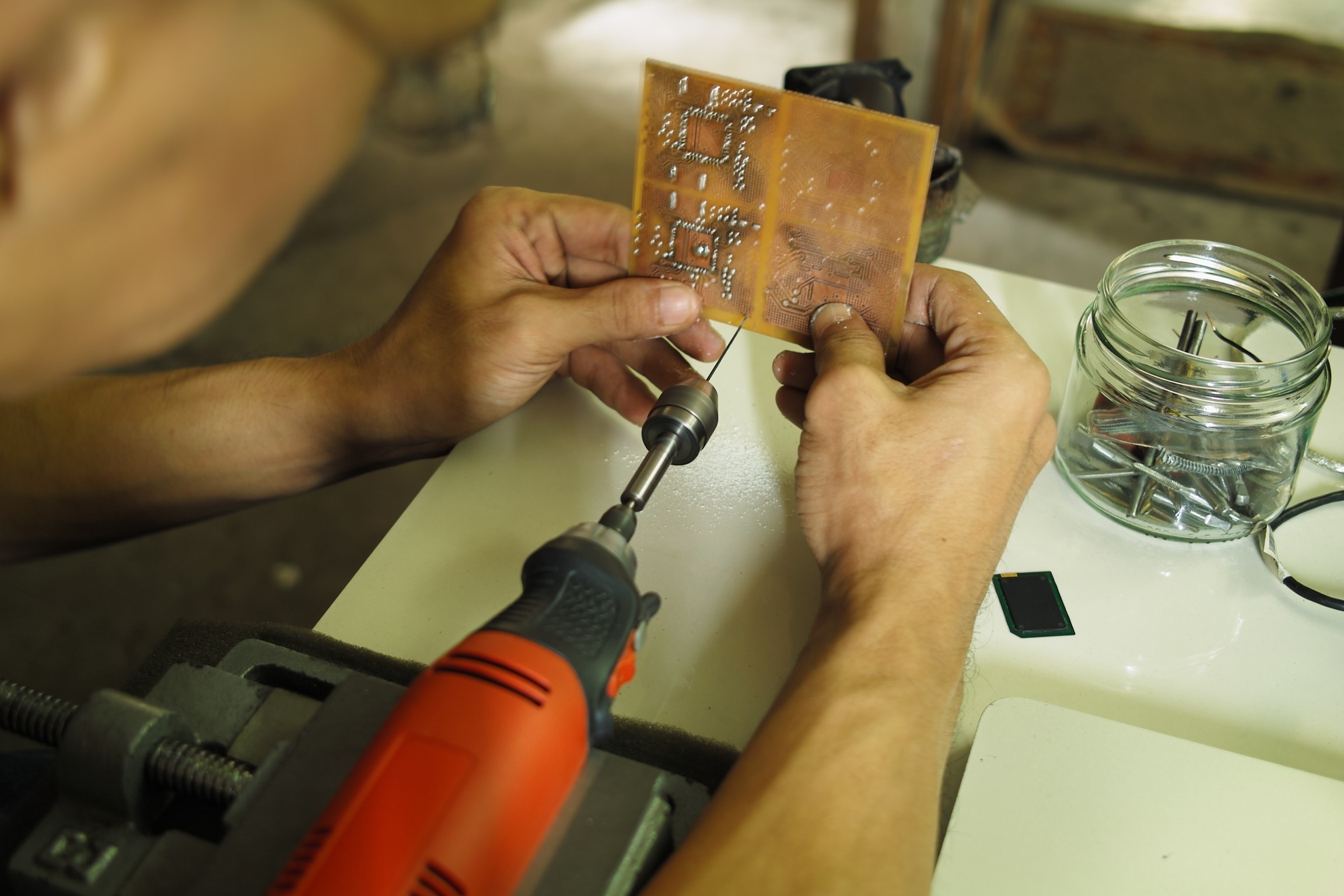
It is the day. Today is the day when we finally assemble the first of three motor controllers. Rather than ruin a perfectly well-etched board, we’ll experiment with a vise-mounted, handheld power tool to drill 0.8mm vias into our test board. The test board is a reject from a previous expose-and-etch attempt that had uneven trace widths.
Haven’t gone out to get an oven toaster yet, so assembly of the first prototype board will have to wait until next weekend. Meanwhile here’s an update of what’s been done so far.